Dimensions in drawings
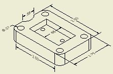
Model dimensions are the dimensions that control the feature size in the part or assembly. They were applied during the creation of the sketch for the feature. In a drawing view, you can display model dimensions in an isometric view or dimensions that are in a plane parallel to an orthographic view.

Use the Retrieve Dimension command to display model dimensions.
Drawing dimensions are dimensions that you add in the drawing to further document the model. Drawing dimensions do not change or control features or part size. You can add drawing dimensions as annotations to drawing views or geometry in drawing sketches.
Use the Drawing Dimensions commands to create and edit drawing dimensions.
You can add text to a dimension. You can also hide the dimension value and display the custom text instead.
 Projected to create dimensions projected to the sheet plane, or select General Dimension Type
 True to create true dimensions placed on model planes. By default, the Projected dimension type is selected for orthographic views, and the True dimension type is selected for isometric views.
Model dimensions can be used only once on a sheet. When you place a view, you can specify whether to display the model dimensions that are planar to the view. You usually include the model dimensions on the first (base) view in the drawing. Subsequent projected views display only those model dimensions that did not display in the base view.
If it is necessary to show a model dimension in another view, you can remove the dimension from the first view, and then apply Retrieve Dimensions to the second view, or add a drawing dimension to the second view.
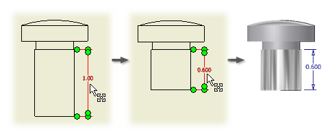
If you set the option to edit model dimensions from a drawing when you installed Autodesk Inventor, you can change the model dimensions from the drawing. Reserve changes in the drawing for minor changes to individual dimensions. If significant changes or changes involving dependent features are required, make the changes in the part model. You cannot change a part in an assembly view.
If you change the size of a part that has multiple occurrences in an assembly or is used in multiple assemblies, all occurrences of the part change.
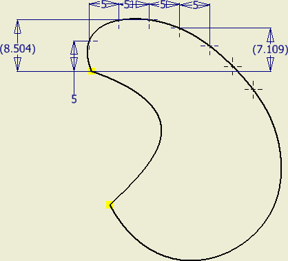
Dimensioning a spline presents unique challenges. Because the shape is constantly changing, applying dimensions for annotation is less obvious than applying dimensions to a prismatic shape. To control the spline shape in the part model, dimensions are applied to fit points and curvature. The following image shows a 2D spline sketch with dimensions on fit points and curvature.
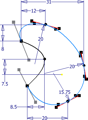
You can use the Retrieve Dimension command in a drawing to recover the dimensions applied to the spline in the model, but these cannot be located at critical dimension locations such as minimum and maximum width.
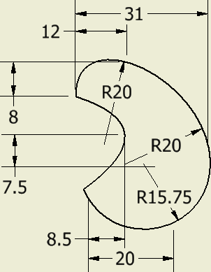
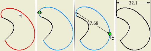
A useful technique you can use to dimension a spline anywhere along the curve is to create a new sketch inside the drawing viewport containing the spline and project the spline geometry into the new sketch. You can then add sketch points and dimension them at any point on the curve as shown in the following image. Use the retrieve dimension command to make the sketch dimensions visible after you exit the sketch.
The drawing dimension commands provide a means to document some of the critical points on a spline. The General, Ordinate, and Baseline dimension commands can add dimensions to the endpoints of a spline. The General and Ordinate dimension commands can also apply dimensions to:
- X Minimum
- X Maximum
- Y Minimum
- Y Maximum
The general dimension command contains a Spline Min/Max snap setting in the context menu. If it is off, you cannot add dimensions to the spline min/max points.
The following image shows general dimensions applied to the X and Y minimum and maximum, and the endpoints of the highlighted spline.
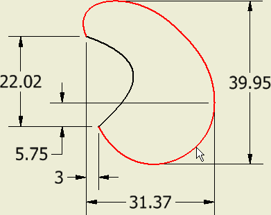
Using drawing dimensions to annotate sketches
When you create a sketch in a drawing, you use sketch dimensions to control its size. When you finish the sketch, use Retrieve Dimensions to display the sketch dimensions on the sheet. The format is controlled by the active dimension style.
You can add drawing dimensions as annotations to the geometry after closing the sketch. These dimensions are associated with the sketch and change if you move or edit sketch geometry.
The dimension style determines the default appearance and properties of dimensions in drawings. It controls the dimension units and tolerances, display of dimension values, arrangement of dimensions in drawing views, style and position of dimension texts, and properties of drawing notes.
The dimension style determines the units of measurement for dimensions in drawings. If the units in the model are different than the units set in the style, dimensions in the drawing are automatically converted to the units dictated by the style.
To select other than inferred annotation plane, right-click and select:
- Horizontal or Vertical dimension type to align the dimension with the coordinate planes of the model.
- Annotation Plane
 Show All Part Work Planes (or Show Visible Part Work Planes). Then select a work plane in the graphic window.
 - Annotation Plane
 Use Sheet Plane to place the dimension on the drawing sheet plane.
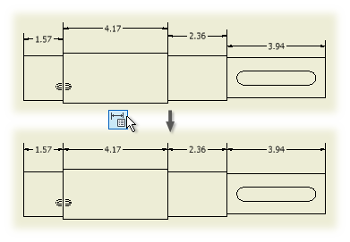
The Arrange command is added to the Annotate panel.
It enables you to arrange groups of selected dimensions (linear, angular, coordinate, chain, true isometric dimensions).
You can select one or multiple dimensions at the same time.
You can select dimensions in the drawing first, and use the Arrange command. Alternatively, you can click the Arrange command first, and then select the dimensions in the drawings.
Select dimensions, right-click, and select Arrange dimensions from the context menu. You can select dimensions that lie along one axis or dimensions arranged along multiple axes.
You can arrange dimensions in one or multiple views.
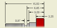 | Use the Dimension command to add drawing dimensions to a view. Drawing dimensions do not affect the size of the part. They provide documentation in the drawing. |
For the current drawing, you can change the layer where dimensions are placed. On the Annotate tab, Format panel, click the arrow to show the layers list and select the layer name.
 Projected to create dimensions projected to the sheet plane, or select General Dimension Type
 True to create true dimensions placed on model planes. By default, the Projected dimension type is selected for orthographic views, and the True dimension type is selected for isometric views.
  |
Tips:
|
Add General dimensions to splines
Add dimensions in isometric views
 Projected from the menu.
Add or edit baseline drawing dimensions
Use Baseline to add individual baseline dimensions to a view or use Baseline Set to add a dimension set.
On the Annotate tab, Format panel, select a dimension style from the Style list. If you want to use the dimension style set in Object Defaults, it is applied automatically.
Available options depend on the selected dimension.
- Select the baseline dimension set in the graphics window.
- Right-click and select an option:
Delete
Removes the selected dimension.
Move Dimension
Select another view and moves the dimension to that view. If no valid attachment points are available in the selected view, a message notifies you and cancels the operation. For more information, see Move dimensions between drawing views.
Copy Properties
Right-click again and select Settings to open the copy Dimension Properties dialog box. Select or clear desired dimension overrides. For more information, see Copy Dimension Properties.
Options
Specify the desired arrowhead position or create a leader. For more information, see Change direction of dimension arrowheads.
Precision
Specify the desired precision setting.
Edit
Opens the Edit Dimension dialog box. You can edit text, set precision and, and set the dimension as an inspection dimension, Optionally. For more information, see Edit Dimensions.
Text
Opens the Format Text dialog box. For more information, see the Format Text.
Add member
Adds additional geometry to the dimension set. Select the point or edge to add to the dimension set. If the dimension does not fall at the end of the dimension set, the members are rearranged to position the new member correctly.
Detach member
Right-click a member and then select Detach Member to remove a dimension from the dimension set.
Add or edit ordinate dimensions
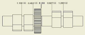
Use the Ordinate commands to add two types of ordinate dimensions to your drawings: ordinate dimension sets and individual ordinate dimensions. Individual ordinate dimensions provide support for imported AutoCAD drawings that contain ordinate dimensions.
Before adding ordinate dimensions to your drawing, you can create or modify a dimension style to assign attributes to the ordinate dimensions.
The dimensions automatically align as you place them. If dimension text overlaps, you can modify or create a dimension style.
Add individual ordinate dimensions
On the Annotate tab, Format panel, you can select a dimension style from the Style list. If you want to use the dimension style set in Object Defaults, it is applied automatically.
On the Annotate tab, Format panel, you can select a dimension style from the Style list. If you want to use the dimension style set in Object Defaults, it is applied automatically.
Edit ordinate dimensions and dimension sets
- To edit an ordinate dimension set, right-click the dimension and then select Options.
- Make Origin moves the origin point to the selected point.
- Allow broken leaders is selected by default. Clear the check mark to disallow broken leaders.
- Positive both directions is selected by default. Dimensions are positive numbers from the zero origin point. Clear the check mark to make negative dimension numbers left of zero origin point.
- Show Direction places an arrow on the origin dimension pointing in the positive direction.
- Reverse direction switches the direction of positive numbers.
- To edit an ordinate dimension leader, click an anchor point and drag it to the desired location.
- Right-click a dimension and select Precision. Select a new precision from the list.
- To edit the origin indicator:
- Click the origin indicator and drag it to the desired location.
- Double-click the origin indicator and enter the precise location in the Origin Indicator dialog box. Autodesk Inventor updates the individual ordinate dimensions to reflect the new position of the origin indicator.
- Right-click the origin indicator or the dimension and select Hide Origin Indicator.
- Double-click the grip point next to the origin indicator to change the origin indicator.
 Show Me how to change the origin indicator in a drawing or dimension style
Use the Chain and Chain Set commands to add two types of chain dimensions to your drawings: chain dimension sets and individual chain dimensions.
Before adding chain dimensions to your drawing, you can create or modify a dimension style to assign attributes to the chain dimensions.
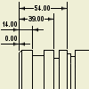
The dimensions are added from the second extension line of the selected Base Dimension in either direction.
Add individual chain dimensions
On the Annotate tab, Format panel, you can select a dimension style from the Style list. If you want to use the dimension style set in Object Defaults, it is applied automatically.
On the Annotate tab, Format panel, you can select a dimension style from the Style list. If you want to use the dimension style set in Object Defaults, it is applied automatically.
Edit chain dimensions and dimension sets
- Select the chain dimension set in the graphics window.
- Right-click and select an option:
Delete
Removes the selected dimension or dimension set.
Copy Properties
Right-click again and select Settings to open the copy Dimension Properties dialog box. Select or clear desired dimension overrides. For more information, see Copy Dimension Properties.
Options
Lock, or unlock dimensions within the chain set. Lock Chain Set is set as default option.
Specify the desired arrowhead position or create a leader. For more information, see Change direction of dimension arrowheads.
Precision
Specify the desired precision setting.
Edit
Opens the Edit Dimension dialog box. You can edit text, set precision and, and set the dimension as an inspection dimension, optionally. For more information, see Edit Dimensions.
Text
Opens the Format Text dialog box. For more information, see the Format Text.
Arrange
Select another view and arrange dimensions to that view. If no valid attachment points are available in the selected view, a message displays, and cancels the operation. For more information, see Arrange dimensions Help topic.
Add Member
Adds additional geometry to the dimension set. Select the point or edge to add to the dimension set. If the dimension does not fall at the end of the dimension set, the members are rearranged to position the new member correctly.
Detach member
Right-click a member and then select Detach Member to remove a dimension from the dimension set.
Dimension to a midpoint or intersection

On drawing views, you can select midpoints of geometry or intersections of overlapping model edges when creating or reattaching dimensions. A midpoint is indicated by a green dot and an intersection is indicated by a yellow dot.
A midpoint is shown for nonclosed geometry but an intersection is shown only for model edges on different objects.
This example shows the intersection of two edges on different objects.
- On the Annotate tab, Dimension panel, click Dimension, Ordinate, or Ordinate Set.
- In the graphics window, click the midpoint or intersection and another line, edge, or point, as required.
- Drag the dimension to the appropriate location and click to place.
- Continue to create and place dimensions as needed, right-click and select Done.
Add dimensions to intersections of extension lines
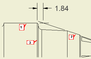
- On the ribbon, click

 .
. - Select the first line (1) to define the intersection.
- Right-click and select Intersection from the menu.
- Select the second line (2) to define the intersection. The lines are extended as needed, and their intersection becomes the first point of the dimension.
- Select a model edge (3) to define the dimension. Alternatively, perform steps 2-4 to define another intersection, or select a point in the drawing view.
- Drag the dimension to the desired position.
- Click to place the dimension in the drawing.
Add dimensions to any point on splines
You can use the general and ordinate dimension commands to apply dimensions to the endpoints and the X and Y Min/Max points of a spline. You can also use Retrieve Dimensions to recover any model dimensions you applied to the sketch. If you must add dimensions to other points on the spline, you can use the following technique.
- Click

 . On the Sketch tab, Display area, verify that sketch Axes are enabled.
 - Save your settings and close the Application Options.
- Select inside the drawing view that contains the spline geometry you want to dimension.
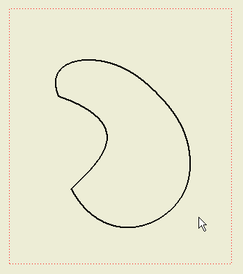
- On the ribbon, click

 .
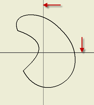
. - If you have the sketch Axes enabled, the sketch axis lines appear in the view as shown in the following image. If the lines are not visible, undo and try again.
- On the ribbon, click

 .
. - Pick the spline geometry to project. Right-click and choose Done when finished.
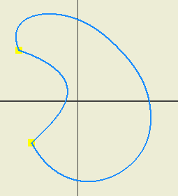
- Click

 . Add points to the spline curve as required.
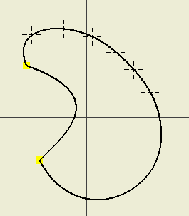
- Click

 . Add dimensions to the points on the spline curve as required.
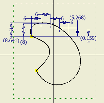
- Choose Finish sketch to exit. The sketch dimensions are no longer visible.
To retrieve the sketch dimensions:
- Right-click in the viewport and choose Retrieve Dimensions from the context menu.
- In the Retrieve Dimensions dialog box, make sure that Select Features is enabled.
- In the browser, expand the view containing the sketch, and select the sketch.
- The sketch dimensions appear in the view. In the dialog box, pick Select Dimensions and select individual dimensions or use a crossing window to select multiple dimensions.
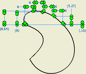
- Click Apply or OK when finished to complete the command.
- Apply dimension formatting if required.

In manufacturing, inspection dimensions are accentuated dimensions that define a part and indicate that it must be checked during quality control before the part is accepted.
- In a drawing, click the Annotate tab.
- On a drawing view, use one or more dimension commands to create dimensions.
- To specify a dimension as an inspection dimension, right-click a dimension and select Edit.
- In the Edit Dimension dialog box, click the Inspection Dimension tab.
- Select the Inspection Dimension check box and then specify attributes:
- Specify None, rounded, or angular to specify the shape. Rounded and angular shapes are represented by images with rounded and angular ends.
- In the Label box, enter the label text.
- In the Inspection Rate box, enter the frequency of inspection. For example, if all parts must be inspected, enter 100%.
- Optionally, click in the Label or Inspection Rate box, and then click the arrow to select a symbol to insert.
- Click OK to close the dialog box and add the inspection attributes to the dimension.
Use model dimensions in a drawing

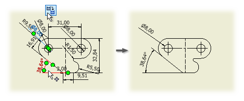
Use the Retrieve command to select valid model feature and sketch dimensions for display on a view. Dimensions and tolerances defined in the model can be displayed in a drawing view. In orthographic views, only those dimensions that are on a plane parallel to the view are displayed. In isometric views, all dimensions are available for selection.
Selectively retrieve dimensions
 |
|
You can also access the Retrieve command by right-clicking a part in the browser or by right-clicking a part in the graphics window.
Remove retrieved dimensions from a view
Automatically retrieve dimensions when you create views
- Click

 Options to access the Application Options dialog box.
 - On the Drawing tab, locate the Retrieve all model dimensions on view placement option. Select the check box to retrieve model dimensions automatically when you place views. Clear the check box to place views without automatically retrieving model dimensions.
Retrieve model dimensions as you create a base view
When you add a base view to a drawing, set the All Model Dimensions option in the Drawing View dialog box. Select the check box to retrieve the model dimensions upon view placement. Clear the check box to place view without retrieving model dimensions.
Add model dimensions to views containing derived part features
- Select a view that contains derived part features.
- Right-click the view, and then select Retrieve Dimensions.
- With Select Source active, expand the view in the browser and select the derived body.
- Select the derived part feature just like any other feature in the part.
- Click each available dimension you want to display. Alternatively, you can click and drag a window to select dimensions. Selected dimensions are highlighted.
In an assembly, annotations can become detached in drawing views when you promote or demote a component in the browser structure or replace or delete components. Use Auto-Reattach Orphaned Annotations to preserve these feature-based annotations.
- Click

 to access the Document Setting dialog box.
 - On the Drawing tab, in the Invalid Annotations box,
- Select the Highlight check box.
- Select the Preserve Orphaned Annotations check box.
- Click Feature-based Annotation Capture Color and select a color to identify the invalid annotations and then click OK.
- Click OK to close the Document Settings dialog box.
- In the drawing view, annotations to reconnect are shown in the highlight color. Select one or more annotations.
- Autodesk Inventor reconnects annotations with valid attachment points.
If the annotation cannot be reconnected, the Design Doctor opens and you can select one or more options for treatment.
Edit model dimensions from a drawing
 | You can make minor changes to a part by editing the model dimensions and tolerances in the drawing. When you edit a model dimension, the part file is updated immediately. |
- Select the dimension to change.
- Right-click, and then select Edit Model Dimension from the menu.
- Enter the new dimension in the edit box.
- To change the dimension tolerances, right-click in the edit box, and then select Tolerances.
Measure distance and angle in drawings
Use the Measure commands on the Tools tab in drawing files to measure distance and angle of geometry within a view, active sketch, and draft. For example, you can measure:
- The length of an edge.
- The diameter of a cylindrical face or edge.
- The circumferential length or radius of an arc.
- The distance between points or other geometry.
- The angle between two pieces of geometry.
- The position of a point relative to the origin of the active coordinate system.
Measure linear distance or length
Linear measurements are displayed in the Measure dialog box as you make them. The title of the box changes to reflect the type of measurement.
- On the ribbon, click

 .
. - In the graphics window, click to select geometry to measure. The length is displayed beneath the Measurement box.
- To measure the distance between points, click to select the first point, and then click to select the second point or use the select other command to navigate to the second point. When you select the second point, the distance between the two geometries is displayed and the length of the last line selected is displayed in the list.
- In the Measure Distance dialog box, click the arrow to select a Precision option.
Angular measurements are displayed in the Measure dialog box as you make them.
- On the ribbon, click

 .
. - In the graphics window, click to select the geometry to measure.
- To measure the angle between two lines or edges, click to select one, and then click to select the other.
- To measure the angle between two points, click to select two points that define a line, and then click the third point to define the angle.
Accumulate the values of several measurements
You can add the values of several linear measurements to calculate a total measurement.
- On the Tools tab, Measure panel, click Distance or Angle.
- In the graphics window, click to select the geometry or distance to measure. The measurement is displayed in the Measure Distance dialog box.
- In the dialog box, click the arrow, and then select Add to Accumulate.
- Continue adding measurements to accumulate.
- When the desired measurements have been added, click the arrow, and then select Display Accumulate. The sum of the measurements is displayed in the dialog box.
Move dimensions between drawing views
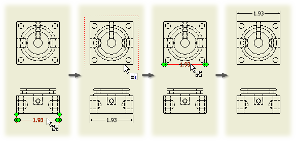
You can move a dimension from one drawing view to another drawing view, as long as attachment points are available in the target view. Any dimension created with the Dimension command or recovered from a model can be moved.
In this example, the overall linear dimension 7.32 can be moved to the projected view because attachment points are available and the dimension does not change type and value.
Linear diametric dimensions behave as linear dimensions instead of diametric dimensions, so that a diameter dimension created in the side view of a cylinder can be moved to the top view of the cylinder. Diametric, radial, and angular dimensions can only be moved to a parallel view.
You can move dimensions between views of the same model on one sheet:
- Linear dimensions (aligned, vertical, and horizontal)
- Diameter dimensions (both linear and the dimensions with leaders)
- Radius dimensions
- Angle dimensions
- Right-click a dimension in a drawing view and select Move Dimension.
- Click the target view.
The dimension moves to the target drawing view with its attributes intact, including text position, extension line, text and terminator overrides, precision and tolerance settings, inspection dimension settings, and dimension style and layer.
Copy all dimension properties
- On a drawing view, right-click a dimension and select Copy Properties.
- Click one or more target dimensions. Properties are copied to the dimensions, which are reformatted with the properties from the first dimension.
- Right-click and select Done to quit.
Copy specified dimension properties
- On a drawing view, right-click a dimension and select Copy Properties.
- Before you click the target dimension, right-click and select Settings to show the Copy Dimension Properties dialog box.
- In the Copy Dimension Properties dialog box, all check boxes are selected by default. Clear the check box of properties you do not want to copy and click OK.
- Click one or more target dimensions to copy the properties. Dimensions are reformatted with the properties specified in the dialog box.
- Right-click and select Done to quit.
Display and edit drawing dimension precision and tolerance
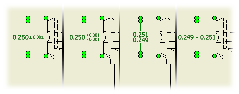
You can specify precision and tolerance for individual dimensions in a drawing.
- Right-click the dimension, and then select Edit from the menu.
- In the Edit Dimension dialog box, click the Precision and Tolerance tab.
- In the Tolerance Method list, select the tolerance type from the list. When you select the type, the associated tolerance value boxes are available to edit.
- In the Precision box, select a precision level for primary units and primary tolerance.
- When values are updated, click OK.
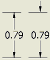
Change direction of dimension arrowheads
On drawing views, you can change the direction of one or both arrowheads to inside or outside the extension line.
For these dimension types, you can specify if both arrowheads are inside or outside the extension lines:
- Linear
- Angular
- Radial
- Diameter
- Baseline and baseline set
Change arrowheads individually
For these dimension types, you can specify the direction of each arrowhead:
- Linear
- Angular
- Baseline and baseline set
The selected arrowhead switches to the opposite direction. For example, if an arrowhead points inside, it changes direction to point outside.

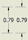
Use Arrange to arrange group of selected dimensions in a view. You can arrange linear, angular, true isometric, and individual baseline and ordinate dimensions.
You can select one or multiple dimensions at the same time.
You can select dimensions in the drawing first, and then execute the Arrange command from the ribbon, or from the context menu. Alternatively, you can click the Arrange command first, and then select the dimensions in the drawings.
You can select dimensions that lie along one axis or dimensions arranged along multiple axes.
You can arrange dimensions in one or multiple views.
Arrange dimensions along the same axis
Adds drawing dimensions to a view. Drawing dimensions do not affect the size of the part, they provide documentation in the drawing. Drawing dimensions are expressed as numeric constants.
Use the Edit Dimension dialog box to edit dimension text, precision and tolerances, and inspection dimension format.
| Access: | Right-click a drawing dimension and select Edit from the menu. Or, double-click a drawing dimension. |

Specifies tolerance format for the selected dimensions in a drawing. Settings on the Precision and Tolerance tab override the settings of the associated dimension style in the current drawing.
| Model Value | Shows the model value of the dimension. |
| Override Displayed Value | Select the check box to turn off the calculated model value and allow entry of an override value. Clear the check box to restore the default calculated model value. |
| Tolerance Method | Specifies the tolerance method for the selected dimension. Scroll through the list and click to select a method. The tolerance method determines which other options in the dialog box are available. |
| Upper | Sets the value for the upper tolerance. A value with a two-part sign of operation represents a range of tolerance. A value with a single sign of operation is either added to or subtracted from the nominal value. If a value has a single sign of operation, you can click to change the sign. |
| Lower | Sets the value for the lower tolerance. A value with a two-part sign of operation represents a range of tolerance. A value with a single sign of operation is either added to or subtracted from the nominal value. If a value has a single sign of operation, you can click to change the sign. |
| Hole | Sets the tolerance value for the hole dimension when using Limits and Fits tolerance. Click the arrow, and then choose the tolerance from the list. |
| Shaft | Sets the tolerance value for the shaft dimension when using Limits and Fits tolerance. Click the arrow, and then choose the tolerance from the list. |
| Precision | Values are truncated and rounded to the specified precision. Click the arrow and select from the list. |
| Primary Unit | Sets the number of decimal places for the primary units of the selected dimension. |
| Primary Tolerance | Sets the number of decimal places for the primary tolerance of the selected dimension. |
| Alternate Unit | Sets the number of decimal places for the alternate units of the selected dimension. |
| Alternate Tolerance | Sets the number of decimal places for the alternate tolerance of the selected dimension. |

| Inspection dimensions are used during the quality control process. They are formatted specifically to indicate which dimensions must be checked before accepting a part. The dimension includes a label and an inspection rate. | |
| Inspection Dimension | Designates the selected dimension as an inspection dimension and activates inspection options. |
| Shape | None Specifies no border shape surrounding the inspection dimension text.
|
| Label/Inspection Rate | Label contains text placed left of the dimension value. Click in the box and enter desired label text. Inspection Rate contains a percentage placed right of the dimension value. Click in the box and enter the inspection rate text. Symbol places the selected symbol in the active label or inspection rate box. |

Creates ordinal reference dimensions. Use any point, center point, or straight edge as a location node for the Origin Indicator. You can also define an Origin Indicator and place it anywhere on the part or assembly view, or anywhere within the bounds of the view.
The dimensions are parametrically tied to the part or assembly, and update when you alter the dimensional location of the referenced feature. However, ordinate dimensions are only for reference. You cannot use them parametrically to alter the part or assembly.
| Access: |    |
Right-click an ordinate point to access the context menu.
Hides origin indicator.
Right-click an ordinate point to access the context menu.
Opens the Dimension Tolerance dialog box so that you can add tolerance notation to the selected member.
Right-click an ordinate point to access the context menu.
Opens the Format Text dialog box so that you can add text to the selected member.
The origin indicator marks the origin point in a drawing view.
You specify the primary position of the origin indicator when you first create ordinate dimensions or a hole table in the drawing view. If you move the origin indicator to a new position, the origin point is moved accordingly and all associated ordinate dimensions and hole tables update automatically.
| Access: | Double-click the origin indicator in a drawing view. |
| Relative X: | Specifies the offset of the origin indicator from its primary position in the X direction. |
| Relative Y: | Specifies the offset of the origin indicator from its primary position in the Y direction. |

Creates ordinal reference dimension sets. Any point, center point, or straight edge can serve as a point of origin. The dimensions are parametrically tied to the part or assembly, and update when the dimensional location of the referenced feature is altered. However, ordinate dimension sets are reference-only and cannot be used parametrically to alter the part or assembly. All dimensions in an ordinate dimension set share the same dimension style.
| Specify placement options for the ordinate dimension set. Right-click to access context menu. | |
| Allow Broken Leaders | Allows the leaders for members of the set to have vertices. Select Allow Broken Leaders to add movable vertices to the leader lines. Clear the check mark to maintain or reset straight leader lines. |
| Positive Both Directions | Creates positive integers for ordinate dimensions regardless of position relative to dimension origin. Clear the check mark to specify negative integers for dimensions to the left of or below the dimension origin. |
| Show Direction | Switches visibility of positive integer direction indicator. |
| Align Members | Sets the dimensions in the set in horizontal or vertical alignment. Select Align Members to maintain or reset the alignment. Clear the check mark to allow horizontal and vertical movement of the dimensions. |
| Show Origin Indicator | Shows origin indicator. |
| Hide Origin Indicator | Hides the origin indicator. |
| Changes the relationship among the members of the ordinate dimension set. Hover over appropriate set member and right-click to access context menu. | |
| Continuous Running | Switches visibility for continuity line between set members. |
| Reverse Direction | Reverses direction of positive integer direction indicator. |
| Make Origin | Sets the selected member as the origin of the dimension set. |
| Add Member | Adds a member to the dimension set. Select a point and place the new member. |
| Delete Member | Deletes the selected member from the dimension set. |
| Adds text or tolerance information to the selected member of the dimension set. | |
| Tolerance | Opens the Dimension Tolerance dialog box so that you can add tolerance notation to the selected member. Click the dimension, right-click, and then select Tolerance from the menu. |
| Text | Opens the Format Text dialog box so that you can add text to the selected member. Click the dimension, right-click, and then select Text from the menu. |

Use Retrieve Dimensions to choose the model dimensions selectively to display in a drawing view.
Model dimensions are the dimensions that control the feature size in the part. They were applied during the sketching or creation of the feature. In a drawing view, you can display model dimensions that are planar to the view.
- Drawing dimensions are dimensions that you add in the drawing to further document the model. Drawing dimensions do not change or control features or part size. You can add drawing dimensions as annotations to drawing views or geometry in drawing sketches.
- Drawing dimensions are displayed using the Drawing Dimensions commands.
| Select View | Select a view to retrieve dimensions for. |
| Select Source | Specifies the type of selection set to be made. You can pick a specific part, feature, or sketch associated with the selected view. Once a selection is made in the view, only valid dimensions from the selected source are previewed and selectable. |
|
| Select Features: Allows for the selection of features, sketched, or view geometry only. |
|
| Select Parts: Allows for the selection of parts only. |
|
| |
| Select Dimensions | Selects dimensions to display. Click Select Dimensions, and then select the dimensions to retrieve. |
On the Tools tab, use the Measure commands to measure distance and angles within a specified view. Results are displayed in the measurement box.
| Access: |       |
From the measure box, click the arrow to list options.
| Restart | Clears the measurement from the Measurement box so that you can make another measurement. |
| Measure Distance | Measures length of a line, length of an arc, distance between points, radius and diameter of a circle, or position of elements relative to the active coordinate system. |
| Measure Angle | Measures the angle between two lines, edges, or points. |
| Add to Accumulate | Adds the measurement in the Measurement box to accumulate a total measurement. |
| Clear Accumulate | Clears all measurements from the accumulate, resetting the sum to zero. |
| Display Accumulate | Displays the sum of all measurements you added to the accumulate. |
| Precision/ All Decimals | Displays eight formatting values and the option to display all decimals. |
Copies one or more properties from the selected dimension to a target dimension.
| Access: | Right-click a drawing dimension and select Copy Properties. Right-click again and select Settings to show the Copy Dimension Properties dialog box. |
You can copy properties for these dimensions:
- Linear dimensions (placed and recovered from model)
- Angular dimensions (placed and recovered from model)
- Radial and Diameter dimensions (placed and recovered from model)
- Ordinate dimensions
- Ordinate and baseline dimension sets
| Style | Select the check box to replace the style associated with the target dimension with the style of the selected dimension. Clear the check box to retain the current style of the target dimension. |
| Layer | Select the check box to replace the layer of the target dimension with the layer of the selected dimension. Clear the check box to retain the current layer of the target dimension. |
| Dimension Overrides | Specifies which of the properties set in the Edit Dimension dialog box to copy. Those settings generally override the defaults specified in the dimension style. Select the Text check box to copy the text overrides to the target dimension. Select the Precision and Tolerance check box to copy the overrides specified on the Precision and Tolerance tab of the Edit Dimension dialog box. Select the Inspection check box to copy the inspection dimension attributes specified on the Inspection Dimension tab of the Edit Dimension dialog box. Select the Arrowhead Shape check box to copy the arrowhead shape to the target dimension. Select the Arrowheads Inside/Outside check box to copy the arrowhead position from the selected dimension to the target dimension. |
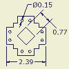




 Specifies rounded or angular ends as the desired shape of the inspection dimension.