Lip features
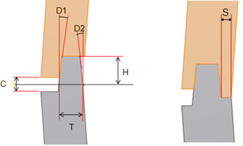
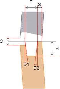
Lip and groove features are often part of a plastic product design. They are used to join two parts precisely at the parting line along the walls. The feature usually consists of two separate elements that precisely mate: the lip itself and the groove. The Lip feature allows the creation of alternatively both elements based on the path along the wall and the geometric parameters.
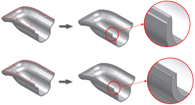
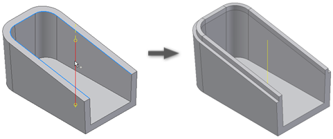
The path consists of a set of smoothly connected boundary edges (tangent continuous). You can select more than one path in the same Lip/Groove feature, provided the Lip face is unique and tangent continuous. For example, you can choose the face of the thin wall where the Lip/Groove lies. You can also select the lip face as the guide face.
Guide face vs. pulling direction
You can refer to the Lip/Groove as the Guide Face (the face on the thin wall section). In this case, the Lip/groove cross section stays at a constant angle with the Guide face along the entire path.
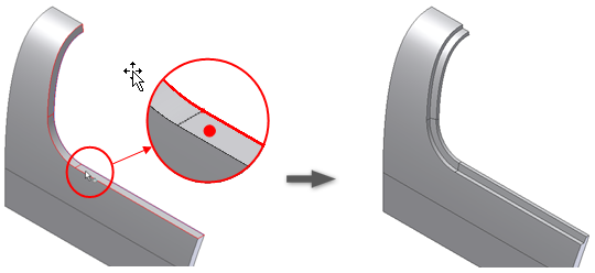
Alternatively, you can refer the Lip/Groove to a Pulling direction. In this case, the Lip/Groove cross section stays parallel to the selected pulling direction along the entire path.
It is also possible to limit the extension of the Lip/Groove to one or more portions of the path. Select two or more limiting elements (points and planes) and the sections to keep or discard.
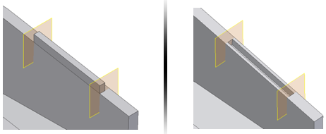
Build a lip feature on multiple paths
Limit the lip extension on one of the paths to two trimming planes.
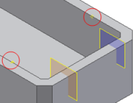
- Create or import a thin-walled part like the one in the following image.

- Define two work planes and two work points (see the red circles) along the path.
- On the ribbon, click


 .
. - Select the two paths (shown in blue and red in the picture).
- Select the Z axis as the Pull direction.
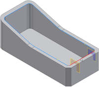
- Use the manipulators on the preview to adjust the Lip cross section and the clearance volume. You can drag the cross section to a more convenient location along the path.
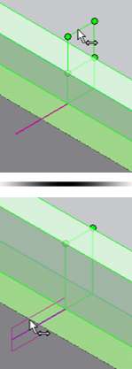
- Expand the Path Extents selector, and select the two planes and the two points. At first, the Lip algorithm makes a tentative choice of sectors. Use the green and yellow dots to choose which sections to keep or remove.
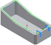
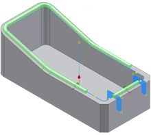
- Click the green or yellow dots until the configuration is like the one in the picture.
- Click OK.
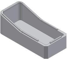
Creates a Lip or Groove feature on the thin wall of a part.

| Path Edges | Selects one or more paths. Each path must be tangent continuous. All the paths of the same Lip/Groove must stay on a tangent continuous face. |
| Guide Face | Selects the Guide face. The Guide face has the path edges on its neighborhood. If selected, keeps the cross section of the Lip/Groove at a constant angle along the path. |
| Pull Direction | Expands to display a selection arrow. Click to select the Pull direction of the Lip/Groove. It is alternative to the Guide Face. When selected, ensures that the Lip/Groove cross section stays parallel to it along the entire path. |
| Path Extents | Expands to display a selection arrow. Click to select the elements to trim the Lip/Groove against. The same selector allows the selection of both the trimming elements and the sections of the path to keep or remove. Use the green and yellow dots to determine which portions of the path to keep or remove. |
The Lip tab holds the geometric parameters input for the Lip type. In alternative to a precise input in the text box, use the manipulators that allow the interactive dimensioning of all the parameters.

The Lip tab has the input text boxes for the following:
