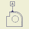
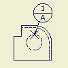
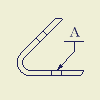
Symbols, sketched symbols, and blocks
You can use symbols, sketched symbols, and blocks to annotate drawings. Symbols are predefined annotations such as surface texture, features control frame, or datum identifier. Sketched symbols are user-defined annotations. Blocks are AutoCAD block objects.
In the browser, click the Drawing Resources folder, and then click the Sketched Symbols folder to see a list of available symbols. After you place a symbol, each instance is listed in the Sketched Symbols browser folder for the current sheet. Define your own folders, under the Sketched Symbol folder, to organize your symbols.
Here are some guidelines to help you create and use sketched symbols:
- Insertion Points snap to other drawing entities and can be used to move, rotate, and resize placed symbols.
- Use the symbol connection points to connect other drawing entities to sketched symbols.
- Create sketch geometry with commands on the Sketch tab, and then constrain and dimension it.
- Include block definitions from a translated AutoCAD file. Nested blocks are exploded into a single sketched symbol. Translated entities are sketched lines and arcs.
- Translate any 2D geometry in an AutoCAD file into a sketched symbol.
- Bitmaps (.bmp files). Bitmaps are OLE objects that can be linked to the drawing or embedded.
When you edit the .bmp file, a linked bitmap image in the sketched symbol is updated automatically. If you embed the bitmap, the copy in the drawing is not updated when you edit the .bmp file.
- Sketched symbols can be associated with model properties. If a leader is deleted, the symbol loses its model association, but restoring the leader can recreate the association.
Instead of deleting a leader, consider turning off its visibility. Invisible leaders retain symbol association with model properties.
- You can insert prompted entries in sketched symbols. If two or more prompted entries are included in a sketched symbol, you can reorder prompted entries: Right-click the sketched symbol in Drawing Resources and select Reorder Prompted Entries from the menu. Then change the order of prompted entries in a dialog box.
You cannot create AutoCAD blocks in Inventor. If blocks exist in an AutoCAD dwg file then they will be available when the file is opened in Inventor. You can also import AutoCAD blocks using the Import Block command. Blocks can only be imported to .dwg files. The block definition is not editable in Inventor.
In the browser, click the Drawing Resources folder, and then click the AutoCAD Blocks folder to see a list of block definitions. After you place a block, each instance is listed in the AutoCAD Blocks browser folder for each sheet.
Here are some guidelines to help you use blocks:
- Block instances can be placed, scaled, moved, and rotated within a drawing sheet.
- Attributes values on block instances can be modified. Right-click on the block and select Edit Attributes.
- Each block instance has a Static property. If the Static property is disabled, grip points are displayed when the block is selected. Use the grip points to rotate and scale the block. If Static is enabled, the grips are not displayed.
- The properties (color, line type, and line weight) can be modified for a block depending on the setting in the block definition.
By Layer | The object inherits the properties of the layer the block is placed on. |
By Block | The object inherits property overrides for the block, then properties of the layer. |
Override | The object maintains the property and does not inherit properties from the layer or property overrides. For example, you set the object property to red in the block definition, the object will always be red. |
In drawings and drawing templates, expand the Drawing Resources folder in the browser to show available symbols in the Sketched Symbols folder. A sketched symbol can contain geometry, text, iProperties, and imported bitmap images. New sketched symbols are added to the Sketched Symbols folder.
- Open a drawing file or drawing template.
- On the ribbon, click

 .
.If you prefer, right-click the Sketched Symbols folder in the browser and select Define New Symbol.
- Use the commands on the Sketch tab to create the symbol.
- To add an insert point to the sketch,
- To add connection points to the sketch,
- Right-click and select Save Sketched Symbol. Enter the new symbol name in the dialog box. The symbol is added to the Sketched Symbols folder in the browser.
- To make sketched symbols available to all new drawings, add them to the template you use to create drawings.
- To assign symbols to a specific layer, use the Style Editor to modify the Object Defaults style.
- If needed, use the Drawing Resource Transfer Wizard to copy symbols from a drawing to another drawing or template file.
- To place and move a sketched symbol precisely on a drawing, add one insert point and several connection points.
- To update all symbols of one type, right-click a symbol and select Edit Definition. The changes are applied to all symbols of that type in the drawing.
- To reorder prompted entries included in a sketched symbol, right-click the sketched symbol in the Drawing Resources folder and select Reorder Prompted Entries from the menu. Available only if 2 or more prompted entries exist in the sketched symbol.
Define folders under your Sketched Symbols folder in the drawing browser. Use them to group your symbols as dictated by your design needs. You can choose to populate your drawing browser with folders before you create symbols. Then, as you create symbols, you move them into the appropriate folders. Alternatively, you can create all symbols, then define your folders and move the symbols into them. Use these techniques, or a combination thereof, to order your symbols in the drawing browser.
You have two methods available to create your symbol folders. You can create empty folders, or pre-select symbol nodes and add them to new folders. User-defined symbol folders are represented by distinctive icons ( Open Folder: ![]() : Closed Folder:
: Closed Folder: ![]() ) and they exhibit the same open and close behavior as other Inventor browser folders.
) and they exhibit the same open and close behavior as other Inventor browser folders.
Right-click the Sketched Symbols folder, or one of your user-defined folders, and select Create New Folder. The new folder is created as a child node of the folder on which you right-clicked.
Select sketched symbol nodes, right-click and select Add to New Folder. To add multiple nodes simultaneously, you can select nodes in a contiguous or non-contiguous group then add them to the new folder.
Edit folders: drag and drop behavior
You can drag and drop single or multiple browser nodes into your folders. Likewise, you can remove nodes from your folders. The drag and drop behavior is similar to that of the Windows Explorer.
You can open the Symbols dialog from your folder nodes and place symbols in your drawing. Right-click a folder or symbol node and select Symbols. You cannot drag symbols from your folders and drop them into the drawing window.
Right-click your symbol folder and select Delete Folder. The folder is deleted, but the folder items remain. You cannot simultaneously delete multiple folders.
- Copy and paste does not support user-defined symbol folders. As a result, if you copy and paste the Sketched Symbols folder or a drawing sheet, the sketch symbols within your folders are pasted, but your folders are not. Consider the creation of drawing templates in which these common folders and symbols are already defined.
Add a sketched symbol to a drawing
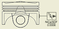 | You can add sketched symbols as annotations to the active drawing file. In the browser, available symbols are listed under Sketched Symbols in the Drawing Resources folder. |
After you place symbols in a drawing, the browser lists each instance in the Sketched Symbols folder for the sheet.
You can create sketched symbols. New symbols are available only in the current drawing, but symbols created in a template are available to all drawings that use that template.
Add a sketched symbol to the active sheet
Stack a symbol to another symbol
- In the browser, right-click the Sketched Symbols in the Drawing Resources folder, and then click Insert.
If you prefer, double-click the symbol in the Sketched Symbols folder.
- Click in the graphics window to place the symbol.
- Continue placing symbols. When you finish, right-click, and then select Done.
The symbol is placed using the default scale and rotation angle and leader setting. Right-click and select Edit Symbol to modify settings.
Move, rotate, or resize a symbol
- Select a sketched symbol in the graphics window to show its points.
- Click a point, and do one:
- To move the symbol, click the green point, and then drag to the appropriate location.
- To rotate the symbol, click the blue dot, and then drag to the appropriate orientation.
- To resize the symbol, click one of the yellow dots, and then drag to the appropriate size.
 | You can add blocks as annotations to the active drawing file when working in a .dwg file. In the browser, block definitions are listed under AutoCAD Blocks in the Drawing Resources folder. |
After you place blocks in a drawing, the browser lists each instance in the AutoCAD Blocks folder for the sheet.
You cannot create block definitions in Inventor. Blocks can be created in AutoCAD and imported into Inventor.
Place a block using the AutoCAD Blocks dialog box
- In the browser, expand the AutoCAD Blocks folder in the Drawing Resources folder.
- In the browser, right-click on any block and then click AutoCAD Blocks.
- In the AutoCAD Blocks dialog box, select the block to place.
- Set the scale and rotation angle for the selected block.
- Click OK to close the dialog box, and then click in the graphics window to place the block.
- Continue placing blocks. When you finish, right-click, and then select Done.
Place a block using the Insert command
- In the browser, expand the AutoCAD Blocks folder in the Drawing Resources folder.
- In the browser, right-click the block, and then click Insert.
- Click in the graphics window to place the block.
- Continue placing blocks. When you finish, right-click, and then select Done.
The block is placed using the default scale and rotation angle. Right-click and select Edit AutoCAD Block to modify settings.
Move, rotate, or resize a block
- Select a block in the graphics window to show its points.
- Click a point, and do one:
- To move the block, click the green point, and then drag to the appropriate location.
- To rotate the block, click the blue dot, and then drag to the appropriate orientation.
- To resize the block, click one of the yellow dots, and then drag to the appropriate size.
The color, target size, line attributes, and measurement units of the symbol are determined by the Datum Target style of the layer and object style of the symbol.
Continue placing datum target symbols. When you finish placing symbols, right-click, and then choose Done from the menu to end the operation.
Add a feature control frame symbol
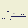 | Use Feature Control Frame to create a feature control frame symbol. You can create a feature control frame with a leader line or as a stand-alone symbol. |
The color, target size, line attributes, and measurement units of the symbol are determined by the feature control frame style.
Add a feature identifier symbol
Sketched symbols can include text, sketch geometry, bitmaps, and model properties.
Sketched symbols with leaders can be associated with model properties. Changes to the model properties are automatically updated with the symbol. If a leader is not created or is deleted, the symbol loses its association to model properties.
Edit symbol values or elements
You can change any value or element that was assigned when a symbol was created.
- In the graphics window, right-click one or more symbols of the same type, and then select the appropriate edit option Select:
- Edit Arrowhead to select a new arrowhead style. Click the arrow to select a new style and then click the green check mark.
- Add Vertex/Leader to add a leader with one or more optional vertices.
- Delete Leader. Use caution; a symbol whose leader has been deleted loses its association with model properties.
- Edit Definition to modify the original symbol sketch. All instances of the symbol update with the changes.
- Edit Symbol to change the selected symbol settings in the Symbol dialog box.
- Properties to modify symbol properties. Change Line Type, Line Weight, Color, and Scale.
- Edit values or geometry as needed. The changes are displayed in the graphics window.
You can move a symbol by lengthening or shortening any segment of a symbol leader line or by moving the symbol, the start point, or any vertex. You can move datum identifiers, callout symbols, and feature control frames by moving their leaders.
Move a datum identifier or symbol
- In the graphics window, move the cursor over the symbol or leader line to display grip points.
- To move the datum identifier or symbol to a new location, drag the grip point closest to it.
- To move the datum identifier or symbol off an edge, drag the base grip point off the edge. Autodesk Inventor creates an extension line for the datum identifier.
- To change the edge the datum identifier or symbol references, drag the base grip point to the desired edge. You can also change the datum identifier so that it references a feature control frame by dragging the base grip point to a feature control frame.
Move a feature control frame
- To move a feature control frame, click the feature control frame, and then drag it to the desired location.
- If you drag the feature control frame parallel to the referenced edge, Autodesk Inventor creates an extension line.
- If you drag the feature control frame away from the referenced edge, Autodesk Inventor creates a leader.
- To make the feature control frame leader collinear with a dimension leader, drag the feature control frame leader arrowhead to the dimension leader arrowhead. To separate the leaders, drag the feature control frame away from the dimension.
You can change the terminator for individual symbols.
- In the graphics window, right-click the symbol, and then select Edit Arrowhead from the menu to open the Change Arrowhead dialog box.
- Click the arrow and select the terminator from the list.
- Click the check mark to change the terminator.
You can copy existing symbols and paste them in your drawings as new symbols to quickly and easily create new symbols.
- In the graphics window, right-click the symbol and select Copy. To select multiple symbols, hold down the Ctrl key as you select symbols.
- Right-click a blank area in the drawing sheet, and select Paste. The copied symbol or symbols are attached to the cursor.
- Click to place the copied symbol or symbols. If you click a highlighted edge or point, the copied symbol is attached to the edge or point.
- Continue placing the copied symbol or symbols. When you finish placing symbols, right-click and choose Done.
On the Annotate tab, Format panel, click the arrow on the Style list and select a style when creating a symbol or to modify a selected symbol. Optionally, edit the default settings for the symbol in Style and Standard Editor.
You can add a branch to an existing leader to enable pointing to multiple locations.
- To add a leader, right-click an existing leader and select Add Leader/Vertex. Click an attachment point on view or sketch geometry and then click the leader line where you want the new leader to attach.
- To add a vertex, right-click select an existing leader and select Add Leader/Vertex. Click a point on the existing leader where you want to add the new vertex and then drag the new vertex point to create a bend in the leader line.
You can edit the position, size, and attributes of block instances. You cannot edit the block definition in Inventor. Open the drawing in AutoCAD to modify the block definition.
You can change any attribute that was assigned when a block was inserted.
- In the graphics window, right-click the block , and then select Edit Attributes.
- Modify the attribute values in the Edit Attributes dialog box.
- Click OK.
You can open the current dwg file in AutoCAD in order to modify block definitions. AutoCAD must be installed on the computer.
- Right-click one or more blocks, and then select Open in AutoCAD.
- Click OK in the Inventor message dialog box. The current file is closed in Inventor and opened in AutoCAD.
- Make the necessary changes in AutoCAD then save and close the file.
- Open the file in Inventor.
You can copy existing blocks and paste them in your drawings as new blocks to quickly and easily create new blocks.
- In the graphics window, right-click the block and select Copy. To select multiple blocks, hold down the Ctrl key as you select blocks.
- Right-click a blank area in the drawing sheet, and select Paste. The copied block or blocks are attached to the cursor.
- Click to place the copied block or blocks.
- Continue placing the copied block or blocks. When you finish placing blocks, right-click and choose Done.
You can create a rectangular pattern of symbols or AutoCAD blocks on a drawing sheet. This command creates multiple copies of symbols or blocks with a uniform distance between instances. This command works with Inventor symbols, sketched symbols, and AutoCAD blocks. The pattern operation is a copy operation and the position of the symbols is not associative.
- Right-click an inserted symbol or block in the browser or in the graphics window and select Pattern Symbols/Blocks.
- Select additional symbols or blocks to pattern.
- The default Direction 1 is horizontal and Direction 2 is vertical. Select the Direction button then select a line in a view or sketch to change the direction.
- Enter the count (number of symbols/blocks) and the spacing (distance between instances) for Direction 1.
- Enter the count and spacing for Direction 2.
Import AutoCAD block definitions
You can import blocks from any dwg file into the current dwg file. A block instance is inserted onto the current drawing sheet and listed in the AutoCAD Blocks folder under the Sheet node in the browser. The block definition is listed in the browser in the AutoCAD Blocks folder in the Drawing Resources folder.
If there is no preview available for the block, a "?" icon is shown in the Block Definitions area of the Import AutoCAD Block dialog box.
When inserting a block with the same name as an existing block in the target file, the new block is inserted as "Copy of [duplicate name]" in the target file.
Dynamic blocks are inserted using the default configuration from the block definition.
Add symbols to prompted entries
- On the taskbar, click Start
 Programs
  Accessories
  System Tools
  Character Map.
 - Double-click the appropriate symbol.
- Click Copy, and then paste the value cell in the Prompted entry or Edit property fields dialog box.
Adds sketched symbols to a drawing sheet. You can rotate and scale the symbols as you add them, add leaders, and associate the symbols to views on the sheet.
Edit Property Fields, Prompted Texts, Attributes
Sets or changes the values of prompted entries and iProperties in a title block, border, or sketched symbol. The iProperties are edited in the Properties dialog box, which is displayed when you click iProperties in the Edit Property Fields dialog box.
If a sketched symbol is created without a leader or edited to delete a leader, it loses its association with model properties. Restoring a leader re-associates the symbol with model properties.
Access: | In the browser, right-click a sketched symbol, border, or the Field Text entry of a title block, and then select Edit Field Text. The dialog box displays automatically when you insert a title block, border, or sketched symbol containing prompted entries in the drawing. |
Use the Reorder Prompted Entries dialog box to change the order of prompted entries included in a drawing resource, for example in a sketched symbol or title block.
The ordered list of prompted entries is displayed in the Edit Property Fields and Prompted Texts dialog box.
Access: | In the drawing browser, right-click a drawing resource which includes 2 or more prompted entries, and select Reorder Prompted Entries from the menu. |
Prompted Entries | Lists all prompted entries included in the selected drawing resource object. Select one or several prompted entries in the list to move them to the desired position. |
Move Down | Moves the selected prompted entry (entries) one row down in the list. Available only if one or several contiguous prompted entries are selected. |
Move Up | Moves the selected prompted entry (entries) one row up in the list. Available only if one or several contiguous prompted entries are selected. |
View blocks are created for each base view and projected view in a DWG drawing sheet when the DWG drawing is saved.
The view blocks display in the browser in the AutoCAD blocks folder under Drawing Resources. You can rotate and scale the blocks as you add them.
Blocks can also be imported from AutoCAD dwg files. Blocks can be inserted onto a drawing sheet similar to sketched symbols.
Access: | In the Model browser, click to expand the Drawing Resources folder and then click to expand the AutoCAD Blocks folder. Right-click one of the entries and select AutoCAD Blocks from the context menu. |
AutoCAD Block list | Shows the AutoCAD Blocks available in the drawing. The default order is the same as the browser. Click to a symbol to select it. Contents can be sorted using drag and drop or right-click in the list and choose Sort by Name. |
Scale | Sets the scale for the block, relative to the drawing sheet. |
Rotate | Specifies the degrees of rotation around the block insertion point. If the block does not have a defined insertion point, rotates the symbol around its center. |
| Static | Specifies if the block can be manually resized and rotated on the drawing sheet. Select the Static check box to turn off scale and rotation grip points on the block. Clear the check box to allow manual resizing and rotation of the block. |
Adds AutoCAD Blocks to a drawing sheet from another dwg file. The block definition is copied into the current dwg file and an instance of the block is inserted onto the current sheet. You can set rotate and scale values in the dialog box.
Creates a rectangular pattern of the selected symbols/blocks. This command works with Inventor symbols, sketched symbols, and AutoCAD blocks. The pattern operation is a copy operation and the position of the symbols is not associative.
Access: | Right-click on any inserted symbol or block and select Pattern Symbols/Blocks. You can right-click on the symbol/block in the browser or the graphics window. |
| | Symbols / Blocks selects one or more symbols, sketched symbols, or blocks to include in the pattern. |

Sets the format for numeric information for measurement units in text, feature control frames, and datum target symbols.
Access: | Select an existing text box, feature control frame, or datum target symbol. Right-click and select Edit Unit Attributes. |
Sets the format for the measurement units to the settings specified by the active standard style when the selected symbol was placed.
Check the box to use the settings in the drafting standard. Remove the check mark to change the settings for the selected text box, feature control frame, or datum target symbol.
Changes the format of the primary units of measure for numeric information in the selected text box, feature control frame, or datum target symbol. | |
Linear | Sets the units of measurement. Click the arrow and select from the list. If no unit type is specified, the unit type of the applicable drafting standard is used. |
Decimal Marker | Specifies the character to use as a decimal. Click the arrow and select from the list. |
Unit String | Displays the primary unit type after the value in the selected text, feature control frame, or datum target symbol. Select the box to display the unit type, clear the check mark to hide the unit type. |
Leading Zeros | Shows or suppresses the display of leading zeros in values. Select the box to display leading zeros, clear the check mark to suppress them. |
Trailing zeros | Shows or suppresses the display of trailing zeros in values. Select the box to display trailing zeros, clear the check mark to suppress them. |
Alternate Units | Displays or hides alternate units. Select the box to display alternate units, clear the check mark to hide them. |
Display style | Sets the display style for alternate units. Click the arrow and select from the list. |
Changes the format of the secondary units of measure for values for numeric information in the selected text box, feature control frame, or datum target symbol. Not available unless Display Alternate Units is selected. | |
Linear | Sets the units of measurement. Click the arrow and select from the list. If no unit type is specified, the unit type of the applicable drafting standard is used. |
Decimal | Specifies the character to use as a decimal. Click the arrow and select from the list. |
Unit String | Displays the alternate unit type after the value in the selected text box, feature control frame, or datum target symbol. Select the box to display the unit type, clear the check mark to hide the unit type. |
Leading Zeros | Shows or suppresses the display of leading zeros. Select the box to display trailing zeros, clear the check mark to suppress them. |
Trailing zeros | Shows or suppresses the display of trailing zeros. Select the box to display trailing zeros, clear the check mark to suppress them. |
Precision | Sets the decimal precision for display of alternate units. Click the arrow and select from the list. |
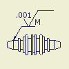 | Specifies the content of a surface texture symbol. The options in the dialog box are determined by the surface texture style. |

