Customize work environments in Autodesk Inventor LT
When you install Autodesk Inventor LT, a default ribbon, browsers, marking menu, and tools are available for each environment. You select the type of environment you want to work in when you create a file or open an existing one.
Each environment has a set of default user interface items. You can customize an environment in the following ways:
- Change the order of ribbon tabs. Click the tab you want to move, drag it to the appropriate position, and release.
- Create a custom panel for each of the ribbon tabs. Right-click any command on tab, and choose Customize User Commands. In the dialog box, add a command. The command displays on a User Commands panel.
- Make additional panels available on a tab. Right-click the ribbon, and select Panels. You can use the same workflow to remove panels from view.
- Switch on large icons.
- Display the ribbon without text.
- Display the marking menus without text or icons.
- Add custom keyboard shortcuts or modify the default shortcuts.
- Add custom command aliases or modify the default aliases.
- Replace default marking menu commands with commands that you choose.
- Delete commands from the marking menu.
You can save your customized ribbon, keyboard, and marking menu settings into a single XML file. Then restore them after you install a new version of Autodesk Inventor LT using the Customize dialog box.
For more information on customizing the ribbon commands, refer to The Ribbon
Save or restore customization settings
After customizing keyboard command aliases and shortcuts, as well as custom ribbon panels and marking menus, you can save the customized settings in an .xml file format. You can restore the customized settings. For example, you can restore your settings after installing a new release of Autodesk Inventor LT.
To save customization settings
- Click

 Customize.
 - Change the command aliases or shortcuts.
- Click Export. The Export Customization Settings dialog box is displayed.
- Navigate to the folder where you want to save the settings. You can create a folder, if necessary.
- Enter a file name, and then click Save.
Add symbols to prompted entries
- On the taskbar, click Start
 Programs
  Accessories
  System Tools
  Character Map.
The Microsoft Windows Character Map dialog box displays.
- Double-click the appropriate symbol.
- Click Copy, and then paste the value cell in the Prompted entry or Edit property fields dialog box.
You can change settings for the active document. To apply the settings to new documents automatically, change the settings in the templates that you use to create documents.
- Click Tools tab
 Options panel
  Document Settings.
 - Click a tab:
- To set units of measurement for a part file, use the Units tab.
- To set snap spacing, grid spacing, line weight display options, and other sketch settings for a part or drawing, use the Sketch tab.
- To set adaptivity or 3D snap spacing for an active part file, use the Modeling tab.
- To set the Repair environment default error check, use the Modeling tab.
- To set the highlighting of invalid dimensions and other annotations in an active drawing file, use the Drawing tab.
- To size the graphics window on file open, use the Modeling tab. The setting only affects the view on file creation and can be set in your template file.
- To set the lighting style and display appearance, use the General tab.
- The Display Appearance settings, General tab, include parameters for edge display, visual style, various shadows, reflection, ground plane, and projection.
- Enter the settings.
- Click Apply to save the changes.
Change the display appearance settings
Display appearance settings control how a document displays in the graphics window when it is opened. To open all documents with the same display appearance, use Application appearance settings. To control how individual documents look when opened, use document appearance settings.
For example, document level control gives you the ability to open one dataset as wireframe and another as shaded. You can open documents in different visual styles without having to alter the appearance settings at the application level. Select Use document settings on the Application Options > Display tab.
New documents have the document appearance settings available. Migrated documents have document appearance settings seeded from the application options appearance settings. After opening a migrated document, you can adjust the display appearance as needed.
To modify document appearance settings:
- On the ribbon, click

 .
. - Click Display Appearance Settings.
- Adjust the parameters in the dialog box.
- Click the Ground Plane settings command to access the parameters for displaying the ground plane.
- Click OK to accept modifications and close the Display Appearance settings dialog box.
- Click Apply to cause the appearance modifications to persist in the document.
- Click Close.
When you modify the document appearance settings, you can use the document settings for display. To take advantage of these document settings, turn on the application option Use document settings.
To establish use of document appearance settings:
- On the ribbon, click

 .
. - Click the Display tab.
- In the Appearance section, click Use document settings.
Thereafter, any document with document appearance settings opens with those settings.
Legacy documents without document appearance settings open with the application options appearance settings. Thereafter, you can specify the document appearance settings to use for the document.
On each tab in the ribbon, you can create one custom panel where you add commands that you want to use from that tab. To generate a custom panel, specify one or more commands to add.
Access: | Ribbon: Tools  Customize Customize  |
Choose commands from | Controls the display of the list of commands. Click the drop-down arrow to narrow the selection. |
Choose tab to add custom panel to | Controls which tab receives the generated custom panel. Click the drop-down arrow to select a tab. |
Add | Adds specified commands to the custom panel in the active tab. |
Remove | Removes specified commands to from the custom panel in the active tab. |
Import | Imports the user-defined panel settings from an .xml file. Click Import to display the Open dialog box. Navigate to the desired file, and then click Open. |
Export | Saves the current user-defined settings in an .xml file. Click Export to display the Save Copy As dialog box. Select a file location, enter a file name, and then click Save. |
Add and modify custom command aliases and shortcuts.
Personalizes the command selection and appearance of the marking menu.

 , and on the drop-down menu, clear the Marking Menu check box.
 Document settings - Standard tab
Sets the active standard for the current document .
Access: |    , and then click the Standard tab in the dialog box. , and then click the Standard tab in the dialog box. |
Adds the selected style to the default standard associated with the document.
Material Style | Click the arrow to select the active material style for the current document. |
Active Lighting Style | Click the arrow to select the active lighting style for the current document. |
Display Appearance | Displays the dialog box where you specify the document display appearance parameters. Enable the use of document display parameters by setting the application appearance option to Use document settings. |
Active Standard | Click the arrow to select the active standard for the current document. Adds the selected standard to the default standard associated with the document. |
Control the appearance of how a model looks when it is opened or when a new view onto the model is opened. To use document based display appearance settings set the Application Option for Appearance to Use document Settings.
| Appearance | These settings apply to model edges whenever they are visible. |
| Display hidden edges dashed | Controls the display of model hidden edges as either solid or hidden lines: Checked Hidden edges are displayed as dashed lines. Not checked Hidden edges are displayed as solid lines. |
| Hidden Edge Dimming | Sets the percent of dimming for hidden edges. Enter the percentage of dimming to apply or click the up or down arrow to select the value. Range is from 10% to 90%. Unchecked and no dimming effect is applied. |
| Depth Dimming | Sets a dimming effect to convey the depth of a model. Select the check box to turn on Depth Dimming. Clear the check box to turn it off. Visual style is wireframe and Depth Dimming set to Off. 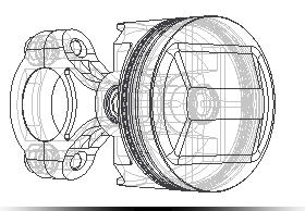 Depth Dimming set to On. 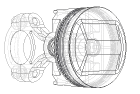 Visual Style is Shaded and Depth Dimming set to Off. 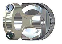 Depth Dimming set to On. 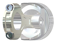 |
| Model Edges | |
| Use part color | Model edge color is derived from the component color. |
| One color | Model edges display using the same color. Clicking the Color button displays the color picker. |
| Display silhouettes | Select the check box to display silhouettes. Clear the check box to suppress the display. When the selected visual style has model edges set to visible, silhouette display is based on this setting. Default is off. Example Silhouettes for active component set to Off. 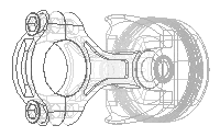 Silhouettes for active component set to On. 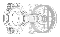 Silhouettes for inactive component set to Off. 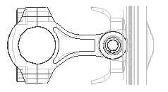 Silhouettes for inactive component set to On. 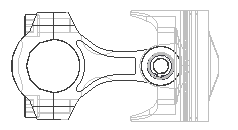 |
| Initial Display Appearance | Sets the model appearance for any new window or view. |
Visual Style Select the preferred visual style used for component display. Projection Sets the view mode to Orthographic or Perspective camera mode. Ground ShadowsWhen checked, displays model ground shadows. Object Shadows When checked, displays model object shadows. Ambient Shadows When checked, displays model ambient shadows. Ground Plane When checked, displays the model ground plane. Ground Reflections When checked, displays model ground reflections. Use Ray Tracing for Realistic Visual Style When checked, enables ray tracing when the Realistic visual style is selected. In the dropdown list specify the default ray tracing mode:
|
Document settings - Sketch tab
On the Document Settings dialog box, sets the default snap spacing, grid settings, and other sketch settings for the active part or drawing file.
Access: |    , and then click the Sketch tab in the dialog box. , and then click the Sketch tab in the dialog box.The active document type determines the available options. |
Sets the spacing between snap points to help with precision when sketching in the active part or drawing. The settings for the two axes can be different. | |
X | Sets the snap distance for the X axis. |
Y | Sets the snap distance for the Y axis. |
Sets the spacing of lines in the grid display for the active part or drawing. The sketch grid is aligned according to the sketch coordinate system. | |
Snaps Per Minor | Sets the distance between minor grid lines relative to the specified snap distance. For example, if you set the X snap distance at 0.0625, and specify 2 snaps per minor, the minor lines are spaced 0.125 apart. |
Major Every Minor Lines | Sets the number of minor lines to appear between major lines. Major lines appear heavier in the grid display. |
Sets the options for line weight display. | |
Display Line Weights | Enables the display of unique line weights in model sketches. Clear the check box to show lines without weight differences. This setting does not affect line weights in printed model sketches. To set the actual line weights in print, use the Sketch Properties toolbar.
|
Document Settings - Modeling tab
Specifies adaptivity, inclusion or exclusion of document history, 3D snap spacing for the active part, and setting for tapped holes.
Access: |    , and then click the Modeling tab in the dialog box. , and then click the Modeling tab in the dialog box. The active document type determines the available options. |
Select to purge rollback document history when you save the file. Clear the check box to regenerate the document history to re-enable fast editing performance. Select Manage tab  Update panel
  Rebuild All.
Sets the algorithm for computing part features.
Select the option to use a comprehensive compute algorithm. It is slower but can produce more accurate feature results in rare cases. Cancel the option to use an optimized feature compute algorithm which significantly improves the performance of Shell, Draft, Thicken, and Offset features.
Maintain Enhanced Graphics Detail
When enabled, graphics information is saved with the file on disk. This detail is used in the graphics display if the Application Options settings is set to Smoother in Application Options.
Controls the model feature size of tapped holes according to the Major, Minor, Pitch, or Tap Drill diameter of the specified thread.
Apply to legacy tapped holes | Updates the setting of existing legacy holes. When you select this option and click OK, all tapped hole features in the document assume the Tapped Hole Diameter setting. The option is available only if any legacy tapped holes exist in the drawing. |
Sets the spacing between snap points to help with precision when 3D sketching in the active part. Controls snap precision when using Move Feature to drag a feature.
Click Settings... to open the UCS Settings dialog box where you can set the UCS naming prefix, define the default plane, and select the visibility of UCS and its features.
Sets the initial visible area when creating a model from a template. Configure this setting in your template files to affect new files. You can set the initial height and width of the graphics window.
The units for the Initial View Extents follow the setting on the Units tab for the template.
This setting will only affect the view on file creation, therefore this setting should be configured in your template files.
Controls the default naming scheme prefix for new solid or surface bodies. Use to specify a meaningful name for each new body at the time of creation. The default prefixes are Solid for solid bodies and Srf for surface bodies.
When selected, automatically checks the model for quality after a manual repair operation such as a boundary patch. Performance is degraded when the option is selected on complex models.
Document Settings - Bill of Materials tab
Specifies Bill of Materials (BOM) settings for the selected component.
Access: |    , and then click the Bill of Materials tab in the dialog box. , and then click the Bill of Materials tab in the dialog box.The active document type determines the available options. |
Default BOM Structure | Sets the default BOM structure for the component. |
Unit Quantity | Displays the Unit Quantity. Unit Quantity is composed of two properties: Base Quantity and Base Unit. |
Base Quantity | Sets the base quantity for the component. Select a parameter to be used as the Base Quantity, and click OK. To edit or add a parameter, click Edit Parameter next to the Base Quantity option. |
Base Unit | Select a Base Unit from the list, and click OK. |
Document Settings - Default tolerances tab
Sets default linear and angular precision levels and tolerances for part dimensions.
Access: |    , and then click the Default Tolerance tab in the dialog box. , and then click the Default Tolerance tab in the dialog box. |
Use Standard Tolerancing Values
Select check box to use the precision and tolerance values set on this tab when creating dimensions.
Export Standard Tolerance Values
Select check box to:
- Copy the tolerances to the iProperties Custom tab.
- Reuse the custom properties in drawings.
Linear and Angular dimensions
Click in a row to add a precision level and corresponding tolerance range for upper and lower values. Add a row for each unique combination of precision level and tolerance range.
Precision | Click the down arrow under Precision and select the number of decimal places. |
Tolerance | Under Tolerance, enter the upper and lower range for the precision level. |
Document settings - Drawing tab
Sets options in the active drawing file or template. To make the settings the defaults for all new drawings, set the options in the templates you use to create drawings.
Defer Updates | Sets the update option for the active drawing. Select the check box to suppress automatic updates. Clear the check box to update the drawing automatically when the model changes. |
Cross Hatch Clipping | Select to have the hatch break about drawing annotations. Notes:
|
Automated Centerlines | Opens the Centerline Settings dialog box so you can set the defaults for automated centerlines to a drawing view. For more information, see Automated Centerlines Settings. |
Invalid Annotations | Annotations may become invalid if the component they are attached to is deleted or replaced. Highlight marks invalid dimensions and other annotations that lose their attachment in the active drawing file. Clear the check box to turn off highlighting. Preserve Orphaned Annotations retains annotations that have become detached from geometry. Clear the check box to remove orphaned annotations. Feature-based Annotation Capture Color specifies a unique color for invalid feature- based annotations. Using the specified color, you can identify annotations that must be deleted and replaced. The remaining invalid annotations can be selected. Right-click and select Reconnect Annotation to attempt reconnection to valid anchor points. |
| Shaded Views | Use Bitmap Sets frequency for using bitmaps on shaded views to Always or Offline Only. Enable Always to increase capacity and improve performance. Bitmap Resolution Sets the image quality for shaded views. Effects file size, graphics appearance, and print quality. Click the arrow, and select from the list |
Dimension Updates | Dimension Text Alignment controls text position for angular and linear dimensions when geometry is updated. View Position maintains text position on the sheet. Sheet Position and Maintain Centered retains centered dimension placement while all other dimensions maintain their positions on the sheet. Percentage of Dimension Line attempts to maintain all dimension text positions relative to the dimension line. |
Properties in Drawing | Additional Custom Model iProperty Source specifies a file that contains custom iProperties and adds names of custom properties to Custom Property - Model list. Properties can be then used in the drawing or template. Click the arrow to select a file from the list, or click Browse to find and select a file. Copy Model iProperty Settings opens the Copy Model iProperty Settings dialog box. Click the command to select model iProperties to copy into the drawing. |
Specifies the iProperties to copy from the model into the active drawing or template when the first drawing view is placed. The copy sets the starting values for iProperties in the drawing. Once copied, the properties do not update automatically when they are changed in the model.
Access: |    , and then click the Drawing tab in the dialog box. Click Copy Model iProperty Settings. , and then click the Drawing tab in the dialog box. Click Copy Model iProperty Settings. |
Model Property Source File | Shows the source model for copied iProperties. |
Copy Model iProperties | Controls if model iProperties are copied to the drawing. Select the check box to copy the model iProperties. |
Copied iProperties | Lists model iProperties. Select the iProperties to copy into the drawing. Clear the check box to keep the existing drawing iProperty. |
All Properties | Selects or clears the selection for all listed iProperties. Select the check box to select all iProperties. Clear the check box to clear the selection for all iProperties. |
Sets the default labels for sheets and sets the colors for elements on sheets in a drawing or template.
Access: |    , and then click the Sheet tab in the dialog box. , and then click the Sheet tab in the dialog box. |
Default Sheet Label | Sets the default label assigned to new sheets in the drawing browser. As a new sheet is added, the label is used with an incremental number (for example, Sheet1, Sheet 2, Sheet3). Click in the box and enter the label. | |
Colors | Sets the display colors for elements of the sheet. Click a color to open the Color dialog box and select the color for the associated element. | |
Sheet | Sets the background color for the sheet. The color of views, symbols, and other elements does not change, so set a background color that provides good contrast. | |
Sheet Outline | Sets the outline color for the sheet. | |
Highlight | Sets the color of highlighted elements (when the cursor passes over them). | |
Selection | Sets the color of selected elements. | |


